
Summary of Analysis Section
In the analysis section, designs are brainstormed and validated on whether it has the possibility of being good or bad. Statics and mechanics of materials are the most used type of analysis, along with solving for max stress, strains, deflections, and shear. All the analysis are being driven by RADD, requirements, analysis, design parameters, and documentation. Requirements mentioned in the report set a standard and a design parameter is found from the analysis portion. All of which aide in coming up with the best possible design and figuring out whether or not the initial idea/design is ideal for the intended use of the Baja RC Car.
Requirements:
1. Upper suspension control arm has less than 3/16” deflection under 20lbs or the full weight of the car.
2. Lower suspension control arm has less than 3/16” deflection under 20lbs or the full weight of the car.
3. The car must be able to make a full 180 degree turn in a 3.5 ft radius circle or less.
4. Car must be able to withstand 3+ vertical drops from 2 ft with spring compression greater than 1/8” from solid.
5. The shocks must have a usable suspension travel of 1” under a static load of 20lbs.
6. Front upper control arms must be able to withstand a side load of 10lbs staying under the critical buckling load with 0” of bending.
7. Suspension articulation (one wheel up, one wheel down) with a difference of 2” in the rear axle.
8. Steering tie rods will have less than 1/16” deflection while steering servo is turning to the left and right.
9. Shocks do not sag more than ½” under the entire weight of the car while stationary, allowing for 0.59in (15mm) of droop and 0.59in (15mm) of up travel.
10. Bulkhead fasteners must be able to withstand 10lbs of shear force while remaining in the elastic region of stainless steel (<205MPa).
11. The rear trailing arms must have less than 1/16” deflection under a 20lb load.

Analysis #1
In analysis #1, the maximum amount of deflection in the rear trailing arm is calculated. The requirement for the rear trailing arm was that it could not surpass more than 1/16" of deflection under a 5lb load coming directly from the shock mounted in the middle. Beam analysis is used to solve for the unknowns. An estimated cross section area that could fit the cars needs is chosen and is used to calculate the maximum amount of deflection. The design parameter from the cross sectional area is that the maximum deflection was far from exceeding the maximum allowable deflection (Ymax = 0.008") with a desirable cross section.

Analysis #2
In analysis #2, the minimum turning angle that the steering servo must be able to steer the front wheels is calculated for the car to be able to make a 180 degree turn (U-Turn) in a 3.5' radius or smaller. The design parameter was such that the maximum wheelbase and track width was 20" long and 15" wide and these inputs in the turning radius equation was that a 25.46 degree turning angle satisfies requirements.


Analysis #3
In analysis #3, the maximum amount of deflection is calculated that the lower control arm can withstand as well as the maximum amount of stress that the lower control arm would be taking on while under a 20 lb force coming from purely the shock. The requirement was that the lower control arm could not surpass more than 3/16" of deflection while still remaining in the elastic region of the stress/strain curve. The design parameter was such that a cross section of the lower control arm where the shock is mounted to be (1" x 1/4") and that fit the desired needs of having a deflection less than 3/16", the maximum calculated deflection was Ymax = 0.111".


Analysis #4
The tie rod must be able to withstand an axial load of 10lbs. Buckling calculations are done to solve for the critical load that the chosen tie rod dimensions can withstand. The slenderness ratio, and transition slenderness ration is calculated to determine if Euler’s or Johnsons methods should be chosen to calculate the critical load. The design parameter was that the cross-sectional area determined that the 8mm diameter rod could withstand the 10lb column load being 5” (Plus or minus 0.050”) long with no buckling/failure.

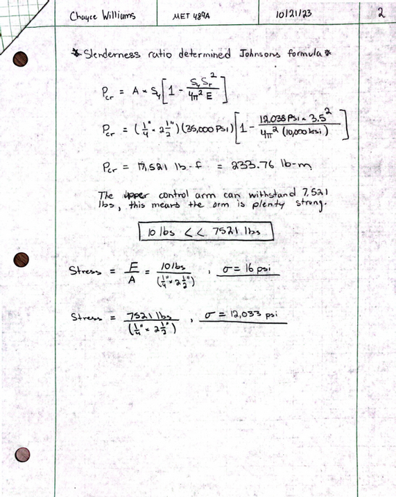
Analysis #5
In analysis 5, the critical buckling force is calculated to ensure that the chosen design meets the stated requirement 1d.6 that the upper control arm can withstand a 10lb side load while moving and remaining under the critical load of the material. Beam buckling equations are used, and to do that the slenderness ration must be determined to decide whether Euler’s or Johnsons method should be used. Johnson’s method is used in this case.

Analysis #6
In Analysis 6, the maximum shear stress that the shoulder screws can withstand is calculated. The requirement 1d.10 was that it needed to be able to withstand the 10lb side loads that the upper and lower control arms take on while remaining in the elastic region (<205MPa <29732psi). The shoulder screws are used to fasten the upper and lower control arms to the bulkhead. The shear capacity is calculated from using ( t = ). The safety factor being 1.5, the maximum tensile stress 70,000psi, and the cross-sectional area being 0.012in2.

Analysis #7
In Analysis 7, the shock spring rate at which the car needs if it weighs 20lbs is calculated. The requirement 1d.7 is such that the RC Baja must have 1” of usable suspension travel to be successful. Along with the requirement 1d.9 that states that the sock must not sag more than ½ inch under static load. These requirements are met by calculating the maximum speed that it will undergo when being dropped 2 feet in the drop test, along with the maximum force that it will undergo doing so. Using this force that it undergoes, the spring rate can be calculated by using k=F/D, K = spring rate F = force, and D = usable travel.

Analysis #8
In Analysis 8, the minimum shock tower thickness is calculated that can withstand the forces acting on the mounting location of the front suspension. The requirement of 1d.4 states that the car must be able to withstand 3+ consecutive drops from 2ft in the air. This means that for the car to handle that kind of scenario the shock tower must be able to handle the forces that are induced on the shock, because whatever forces are acting on the shock, the forces are also acting on the shock tower, as well as the lower control arm (mounting locations of the shock). The total amount of force that acts on the front wheels individually when dropped is calculated and that force is used to calculate the minimum thickness. This is done by using the equation t = F/A, A = base x height, F = force, t = shear strength.

Analysis #9
The requirement for the rear shock tower was that it needed to withstand 20lb static load and be able to withstand 3+ consecutive drops as stated in requirement 1d.4 and 1d.5. The rear shock tower must be able to withstand the forces that will be acting on the car from these requirements, and for the car to work in conjunction with one another the rear shock tower must have a minimum thickness to not fail.

Analysis #10
The rear trailing arms must have mounting locations such that the suspension geometry is at peak performance. If mounting locations are not correct suspension will bind up and the 1” in articulation between wheels will not be achieved in the rear axle that is said to be a requirement. And because the car will also be dropped from 2ft 3+ times the car must also be able to withstand 20+ pound loads. So, in analysis #10, the bearing stress of the mounting tabs for the rear trailing arm is calculated for a 100lb load so that when the car is used, the mounting tabs do not break under force.

Analysis #11
Analysis #11 simulates a person picking up the RC car by the rear shock tower support. To simulate this scenario an analysis is done using mechanics of materials methods. The section of the rear shock tower support is simplified down to a beam therefore allowing for beam deflection formulas being able to be used. Doing so with the chosen design parameter of a cross-sectional area of 1" wide and 0.25" tall the maximum deflection of the support is 0.062". The total amount of stress that the 20lb load with a safety factor of 3 (60lbs) is only 240 psi, and because this part is 3D printed, the material chosen is PLA, and the yield point of PLA is 3770 psi, 240 psi is much lower than 3770 psi so with the design parameter, the design proves trustworthy to be picked up at that point.

Analysis #12
In analysis 12, the steering tie rod critical road is calculated. The tie rod must be able to withstand a total force of 77.16lbs because that is what the chosen servo is rated for. In the analysis, the critical load must be calculated, and to do so, the slenderness ratio, and transitional slenderness ratio must be calculated. And a design parameter chosen to be the diameter of 1/8” 6061 aluminum. 1/8” diameter is the desired size of the tie rods cross-section. With the needed length and 1/8” diameter rod, Eulers equation is used because the slenderness ratio came out to be larger than the transitional slenderness ratio. So, with a design parameter of an 1/8” diameter, the critical load that the tie rod can handle without bending is 84.1lbs.